


How Do Pneumatic Linear Actuators Work? Working Principle, Types and Applications
Many industrial machines need controlled movement to push, pull, lift, clamp or position a component. In automated production lines, this movement often needs to happen repeatedly and at a controlled speed.
A pneumatic linear actuator is one of the devices used to perform these tasks. It converts the energy of compressed air into straight-line mechanical movement. Depending on the design, this movement can extend or retract a piston rod, move a carriage along a guide or operate a linear valve mechanism.
Pneumatic linear actuators are widely used in manufacturing equipment, packaging machines, material handling, process automation and other industrial applications.
But how do pneumatic linear actuators work, and how do you choose the right type for a particular machine?
The answer begins with understanding how air pressure moves a piston inside a cylinder.
What Is a Pneumatic Linear Actuator?
A pneumatic linear actuator is a mechanical device that uses compressed air to generate movement along a straight line.
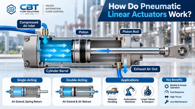
A common design consists of a cylinder barrel, a piston, seals and a piston rod. Compressed air enters the cylinder through a port and creates pressure on the piston. The resulting force moves the piston and transfers movement to the piston rod or attached mechanism.
The rod can then push, pull, lift or position a component.
For example, consider a packaging machine that needs to push a finished product onto a conveyor. A pneumatic cylinder can extend its piston rod to move the product and then retract it so that the next product can be positioned.
The same principle is used in clamping fixtures, assembly equipment, sorting machines, dampers and suitable industrial valve applications.
CBT Flow Solutions Pvt. Ltd. supplies linear actuators and pneumatic cylinders for industrial equipment, including applications involving machines, dampers and linear valves.
How Do Pneumatic Linear Actuators Work?
The working principle is based on the force created when compressed air acts on a piston.
Let us look at the process step by step.
Step 1: Compressed Air Is Supplied
A compressor produces compressed air, which is distributed through the pneumatic system.
Before reaching the actuator, the air may pass through filtration, pressure regulation and other air-preparation equipment. The exact arrangement depends on the installation.
A directional control valve determines where the compressed air enters the actuator and which side is allowed to exhaust.
Step 2: Air Pressure Acts on the Piston
Inside the cylinder, compressed air enters a chamber on one side of the piston.
The pressure creates a force across the piston area. When this force is sufficient to overcome the opposing load, friction and other resistance, the piston begins to move.
The force available depends on the air pressure, effective piston area and mechanical losses.
Step 3: The Piston Moves in a Straight Line
As the piston moves through the cylinder, it transfers linear movement to the connected piston rod.
The rod extends or retracts depending on the air supply and actuator design.
This movement can then be used to operate a machine component, open or close a suitable linear valve, move a damper mechanism or position a workpiece.
Step 4: Exhaust Air Leaves the Cylinder
As the piston moves, air from the opposite chamber must leave through the appropriate port.
The directional valve controls the supply and exhaust paths. Proper exhaust flow is important because restrictions can affect the actuator’s speed and response.
Step 5: The Actuator Reaches Its Required Position
The piston continues moving until it reaches its intended stroke position or encounters the designed end stop.
Some cylinders use adjustable cushioning to reduce impact near the end of the stroke. Sensors may also be used to detect piston position and provide feedback to an automation system.
This completes one movement cycle. The control system can then command another stroke when required.
What Are the Main Parts of a Pneumatic Linear Actuator?
Understanding the main components helps when selecting, installing or troubleshooting an actuator.
1. Cylinder Barrel
The cylinder barrel provides the enclosed space in which the piston moves. Its construction must be suitable for the operating pressure, environment and intended service.
2. Piston
The piston separates the internal chambers and converts air pressure into linear force.
Its effective area is an important factor when calculating the actuator’s theoretical force.
3. Piston Rod
The piston rod transfers movement from the piston to the external load.
The rod must be suitable for the expected force, stroke, mounting arrangement and side loading. Excessive side loading can damage seals, bearings or the rod itself.
4. Seals
Seals help prevent unwanted air leakage between the chambers and around moving components.
Seal material must be compatible with the temperature, lubricant, environment and operating conditions.
5. Air Ports
The ports allow compressed air to enter the cylinder and exhaust from it. Their arrangement depends on whether the actuator is single acting or double acting.
6. End Caps
End caps close the cylinder and provide connections for mounting and pneumatic ports, depending on the design.
7. Cushioning
Some cylinders include cushioning near the end of the stroke. This slows the piston before it reaches the end stop and can reduce impact, noise and mechanical wear.
8. Position Sensors
Certain cylinders allow magnetic or other sensors to detect piston position. These sensors can provide feedback to a PLC or machine controller.
Not every actuator includes all these features, so the specification should be checked before ordering.
Types of Pneumatic Linear Actuators
Different actuator designs are available because machines have different force, stroke, mounting and control requirements.
1. Single-Acting Pneumatic Cylinder
A single-acting cylinder uses compressed air to produce movement in one direction. A spring or an external load provides the return movement, depending on the design.
When the air supply is applied, the piston moves against the spring or load. When the pressure is released, the spring or external force returns the piston.
Single-acting cylinders are often used for short-stroke operations that require work in one powered direction.
Typical applications include:
- Light clamping operations.
- Part positioning.
- Simple pushing tasks.
- Marking and stamping mechanisms.
- Small machine movements.
The return force and available stroke must be considered during selection because the spring occupies internal space and opposes movement.
2. Double-Acting Pneumatic Cylinder
A double-acting cylinder uses compressed air for both extension and retraction.
It normally has two working ports. When air enters one chamber, the piston moves in one direction while air exits the other chamber. Reversing the air supply moves the piston in the opposite direction.
This arrangement provides powered movement in both directions.
Double-acting cylinders are commonly used when the application requires controlled extension and retraction or when an external force cannot reliably return the piston.
Typical applications include:
- Automated assembly machines.
- Conveyor positioning.
- Material handling.
- Clamping and pressing equipment.
- Linear valve and damper mechanisms.
CBT’s Linear Actuators & Pneumatic Cylinders page lists a double-acting pneumatic piston-barrel linear actuator series.
3. Rodless Pneumatic Cylinder
A rodless cylinder produces linear movement without a conventional piston rod extending from one end.
Instead, the piston transfers movement to an external carriage through a mechanical connection or magnetic coupling, depending on the design.
Rodless cylinders can be useful when a long stroke is required but the available installation space is limited.
They are commonly considered for material transfer, positioning and certain automated handling tasks.
The maximum load, stroke, side-load capability and guidance arrangement must be checked for the selected model.
4. Guided Pneumatic Cylinder
A guided cylinder combines pneumatic movement with a guide mechanism designed to support the moving load.
The guides help resist side forces and prevent unwanted rotation. This is useful when the application requires controlled positioning or when the load cannot be supported by the piston rod alone.
Guided cylinders are often used in pick-and-place equipment, clamping systems, assembly machines and handling applications.
The allowable load, moment and stroke depend on the cylinder design.
5. Diaphragm Linear Actuator
A diaphragm actuator uses compressed air acting on a flexible diaphragm to produce linear movement through a stem.
This design is commonly associated with process control valves, where it may be combined with a positioner for controlled adjustment.
The actuator’s force and stroke must match the valve’s operating requirements.
Diaphragm actuators are different from standard piston-cylinder designs, even though both can create linear movement.
How Is Pneumatic Actuator Force Calculated?
Force is an important part of actuator selection.
The theoretical force generated by a pneumatic cylinder is calculated using pressure multiplied by the effective piston area.
Basic formula:
Force = Pressure × Effective Piston Area
For example, consider a cylinder with a piston diameter of 50 mm operating at a pressure of 6 bar.
Six bar is equivalent to 0.6 N/mm².
The piston area is approximately 1,963.5 mm².
The theoretical extension force is therefore:
0.6 × 1,963.5 = approximately 1,178 N.
This is the theoretical force before accounting for friction, pressure losses, spring force or other mechanical resistance.
During retraction, the piston rod reduces the effective area on the rod side. As a result, the theoretical retraction force is usually lower than the extension force for the same pressure and cylinder diameter.
In practice, the actuator should be sized with suitable allowance for the load, operating conditions and required reliability. The manufacturer’s force tables should be used for final selection.
What Affects the Speed of a Pneumatic Linear Actuator?
The actuator’s speed is not determined by pressure alone.
Several factors affect how quickly the piston extends or retracts.
Air pressure: The available pressure affects the force available to move the load.
Airflow: The directional valve, tubing, fittings and exhaust paths influence how much air can enter and leave the cylinder.
Cylinder size: A larger cylinder requires more air to complete the same stroke at the same speed.
Stroke length: A longer stroke generally requires more air and more time to complete when other conditions remain similar.
Load: A heavier load or greater friction can slow movement.
Cushioning: End-of-stroke cushioning reduces impact but can influence the final part of the movement.
Control valve and tubing size: Restrictions in the pneumatic circuit can reduce the available flow.
If accurate and repeatable movement is required, these factors should be considered together instead of increasing the supply pressure without checking the equipment limits.
Where Are Pneumatic Linear Actuators Used?
Pneumatic linear actuators are used in applications that need straight-line movement.
Manufacturing and Assembly
They move, clamp, position or hold components during assembly and production operations.
Packaging Machinery
They push products, move guides, operate cutting mechanisms and position packages in suitable machines.
Material Handling
Pneumatic cylinders can lift, push, pull or position components along a production line.
Pharmaceutical and Food Processing Equipment
Suitable pneumatic cylinders may be used in packaging, handling and auxiliary equipment. The actuator’s materials, cleanliness and environmental protection must match the installation requirements.
Water Treatment and Process Plants
Linear actuators can operate compatible dampers, linear valves and other equipment requiring straight-line motion.
Industrial Valve and Damper Systems
Some process valves and dampers require linear stem movement rather than a quarter-turn rotation. A suitable linear actuator can provide this movement, provided its force, stroke, mounting and control requirements match the equipment.
For applications requiring rotary movement to operate ball valves or butterfly valves, a rotary pneumatic actuator is normally used instead. See CBT’s Pneumatic Actuator range for its industrial rotary actuator offerings.
Pneumatic Linear Actuators vs Hydraulic and Electric Actuators
The three technologies perform similar tasks but use different energy sources and mechanisms.
| Feature | Pneumatic Linear Actuator | Hydraulic Linear Actuator | Electric Linear Actuator |
|---|---|---|---|
| Energy source | Compressed air | Pressurised hydraulic fluid | Electric motor and drive mechanism |
| Movement | Straight-line movement | Straight-line movement | Straight-line movement |
| Typical strengths | Fast movement and simple pneumatic control | High force in compact designs | Controlled positioning and easy integration with electrical control |
| Key considerations | Air supply, air consumption and compressibility | Fluid leaks, hydraulic power unit and maintenance | Power supply, actuator rating and control system |
| Common uses | Automation, clamping, pushing and positioning | Heavy-duty lifting and pressing | Adjustable positioning and motion control |
No technology is best for every application. The choice depends on the required force, stroke, speed, positioning accuracy, duty cycle, environment and total operating cost.
How to Select the Right Pneumatic Linear Actuator
Before purchasing a linear actuator, check the following points.
1. Required Force
Calculate the force needed to move the load, including friction and other resistance. Do not choose the actuator using the load weight alone.
2. Stroke Length
Confirm how far the actuator must move. The available stroke should match the mechanism’s travel without causing unwanted impact or interference.
3. Operating Pressure
Check the minimum and maximum available air pressure. The actuator must produce enough force at the minimum expected pressure.
4. Operating Speed
Consider how quickly the actuator must extend and retract. Airflow, valve capacity, tube length, load and cushioning all influence speed.
5. Single or Double Acting
Choose single acting when powered movement is required in one direction and a spring or external force can provide the return. Choose double acting when compressed air is needed for both directions.
6. Mounting and Space
Check mounting dimensions, alignment, rod-end connections and the space required for the full stroke.
7. Side Loads and Guidance
A piston rod should not be expected to carry large side loads unless the actuator is designed for them. Consider a guided cylinder or separate linear guide where necessary.
8. Environment and Protection
Check dust, moisture, temperature, corrosion and other operating conditions. Verify the actual protection rating and material suitability for the selected model.
9. Feedback and Controls
If the machine needs to know the actuator’s position, confirm whether the selected design supports sensors or other feedback devices.
10. Maintenance and Spare Parts
Consider seal replacement, access for inspection, spare-part availability and the manufacturer’s servicing requirements.
Common Problems With Pneumatic Linear Actuators
Like any mechanical device, pneumatic actuators can develop problems when the air supply, installation or internal components are not suitable.
The Actuator Moves Slowly
Possible causes include low supply pressure, restricted airflow, undersized control valves, air leakage or a load that exceeds the available force.
Check the pneumatic circuit and confirm the actuator’s rated operating conditions.
The Actuator Does Not Complete Its Stroke
The cause may be insufficient force, mechanical obstruction, misalignment, an incorrect stroke specification or a problem with the directional control valve.
Inspect the load and mounting arrangement before changing the operating pressure.
Air Leakage
Damaged seals, loose connections or worn components can cause leakage and reduce performance.
Inspect the system according to the manufacturer’s maintenance instructions.
Uneven or Jerky Movement
Contamination, excessive side loading, misalignment, worn seals or poor flow control can affect smooth movement.
Check the installation and load conditions before replacing the actuator.
Before carrying out maintenance, isolate the equipment, release stored pneumatic pressure and follow the appropriate safety procedures.
Pneumatic Linear Actuators Supplier in India
CBT Flow Solutions Pvt. Ltd. supplies linear actuators and pneumatic cylinders for applicable industrial machinery, dampers and linear-valve applications.
Its Linear Actuators & Pneumatic Cylinders page lists a Neles Easyflow pneumatic piston-barrel linear actuator series with the following published specifications:
- Double-acting configuration for the listed series.
- Maximum operating pressure of 10 bar.
- Force range of 1,147 N to 20,107 N.
- Temperature range of -20°C to +80°C.
- IP67 protection class.
- ISO 15552 / VDMA 24562 mounting interface.
These specifications apply to the listed product series and should not be treated as universal ratings for all pneumatic linear actuators. Confirm the manufacturer’s latest datasheet and exact model before specifying a product.
When requesting a quotation, provide the required thrust, minimum available air pressure, bore, stroke length, speed, mounting arrangement, side-load conditions and feedback requirements.
Frequently Asked Questions
How do pneumatic linear actuators work?
They use compressed air to create pressure on a piston or diaphragm. This pressure generates force and moves a piston rod or connected mechanism in a straight line.
What is the difference between single-acting and double-acting pneumatic cylinders?
A single-acting cylinder uses compressed air for movement in one direction and a spring or external force for the return. A double-acting cylinder uses compressed air to produce both extension and retraction.
What determines the force of a pneumatic linear actuator?
The force depends mainly on the air pressure and effective piston area. Friction, spring force, pressure losses and mechanical resistance reduce the actual force available.
Where are pneumatic linear actuators used?
They are used in manufacturing, packaging, material handling, clamping, positioning, machine automation, and suitable valve or damper applications.
Are pneumatic linear actuators suitable for heavy loads?
They can handle a range of loads, but the correct actuator must be sized for the required force, stroke, pressure and operating conditions. For very high forces, a hydraulic or another suitable drive may be more appropriate.
What is the difference between a linear and rotary pneumatic actuator?
A linear actuator produces straight-line movement, while a rotary actuator produces turning motion. Linear actuators are used for pushing, pulling or positioning, whereas rotary actuators are commonly used to operate quarter-turn ball and butterfly valves.
How do I choose the correct pneumatic cylinder size?
Start with the required force and stroke. Then confirm the minimum air pressure, speed, mounting, side-load conditions, duty cycle and environmental requirements. Use the manufacturer’s sizing data to finalise the selection.
Conclusion
Pneumatic linear actuators convert compressed-air energy into straight-line movement. Inside a common cylinder, air pressure acts on a piston, creating force that moves a piston rod or connected mechanism.
Single-acting cylinders use air for one direction and a spring or external force for the return. Double-acting cylinders use compressed air for both extension and retraction. Other designs, including rodless and guided cylinders, serve applications with different space, stroke and load requirements.
The right actuator depends on more than the nominal cylinder size. Force, stroke, pressure, speed, mounting, side loads and the operating environment must all be considered.
A properly selected actuator can help a machine move consistently, reduce unnecessary stress on components and improve the reliability of the application.
Need a Pneumatic Linear Actuator for Your Application?
CBT Flow Solutions Pvt. Ltd. supplies linear actuators, pneumatic cylinders, industrial valves and flow-control products for a range of industrial requirements.
Share your required force, minimum air pressure, stroke length, operating speed, mounting arrangement and application with our team to help identify a suitable product.
CBT Flow Solutions Pvt. Ltd.
Valves | Automation | Flow Control
Reliable Flow for a Better Tomorrow