


Valve Automation: How It Works, Components, Benefits & Selection Guide
A valve may look like a simple part of a pipeline, but in an industrial plant it often controls something much bigger.
It may start or stop cooling water. It may isolate a chemical line. It may control steam entering a process. It may shut down a gas line during an emergency.
If someone has to walk to every valve and operate it manually, the process becomes slow, difficult to control, and heavily dependent on human action.
This is where valve automation becomes useful.
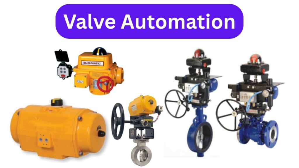
Valve automation allows an industrial valve to open, close, or move to a required position automatically using an actuator and control accessories.
Instead of an operator turning a handwheel or lever, a PLC, DCS, switch, sensor, or control system sends a signal. The actuator receives that command and moves the valve.
It sounds simple, but a reliable valve automation system is more than just putting an actuator on top of a valve.
The valve, actuator, solenoid valve, limit switch, positioner, air filter regulator, mounting arrangement, and control signal all need to work together.
Let us understand the complete system in simple terms.
What Is Valve Automation?
Valve automation is the process of operating an industrial valve automatically rather than manually.
The basic system normally contains two main parts:
- the valve that controls the process fluid;
- the actuator that provides the mechanical movement.
Depending on the application, several additional components may also be required.
These can include:
- solenoid valves;
- limit switch boxes;
- valve positioners;
- air filter regulators;
- position indicators;
- mounting brackets;
- couplings;
- control panels;
- PLC or DCS connections.
When these parts are correctly selected and assembled, the valve can be controlled remotely and can also become part of a larger automated process.
For example, imagine a tank filling system.
A level sensor detects that the tank is almost full.
The signal goes to the PLC.
The PLC sends a command to the automated valve.
The actuator closes the valve.
The incoming fluid stops.
No operator needs to stand beside the valve waiting for the tank to fill.
That is valve automation in practical use.
Why Do Industries Automate Valves?
The biggest reason is better process control.
Manual valves work perfectly well in many applications, but they are not ideal when a valve needs to operate frequently, quickly, remotely, or according to changing process conditions.
Valve automation can help when a valve needs to:
- open and close many times a day;
- operate from a control room;
- respond automatically to sensors;
- move during an emergency;
- maintain a specific flow condition;
- work in an area that is difficult for operators to access;
- become part of a larger automated production process.
A manual valve depends on someone reaching the valve and physically operating it.
An automated valve can respond to a control signal.
That difference becomes very important in large plants.
Main Components of a Valve Automation System
A complete valve automation package may contain several components. Each one has a specific job.
1. Industrial Valve
The valve is the part that actually controls the process fluid.
Common valves used in automation include:
- ball valves;
- butterfly valves;
- plug valves;
- globe valves;
- gate valves;
- control valves.
Ball valves and butterfly valves are especially common in quarter-turn automation because they usually need about 90 degrees of rotation between open and closed positions.
The correct valve must first be selected according to the process media, pressure, temperature, connection type, materials, flow requirement, and shut-off requirement.
Only after that should actuator sizing begin.
2. Pneumatic Actuator

A pneumatic actuator uses compressed air to move the valve.
For quarter-turn valves, rack-and-pinion and scotch-yoke actuators are commonly used.
Compressed air enters the actuator and moves internal pistons. That movement rotates the actuator shaft, which then rotates the valve stem.
Pneumatic actuators can be double acting or single acting.
A double-acting actuator uses compressed air in both directions.
A single-acting actuator normally uses compressed air in one direction and springs for the return movement.
Spring-return actuators can be useful when the valve needs to move automatically to a safe position if air supply is lost.
CBT India’s pneumatic actuator range is particularly relevant to valve automation because the company offers actuator configurations for ball valves, butterfly valves, plug valves, and other industrial applications.
3. Electric Actuator

Not every plant has compressed air available near every valve.
In that case, an electric valve actuator may be a better option.
An electric actuator uses an electric motor and gearbox to move the valve.
Electric valve automation is commonly considered where electrical power is readily available, especially in remote installations or applications where building a compressed-air network would not be practical.
Electric actuators can be used for simple ON/OFF operation or modulating control depending on the model.
For example, an ON/OFF actuator may move a ball valve between fully open and fully closed.
A modulating actuator may move a valve to 20%, 40%, 60%, or another required position based on a control signal.
The correct selection depends on torque, voltage, duty cycle, operating speed, control signal, environment, and required valve movement.
For applications where a complete electrically operated ball valve is preferred, a 2-way metal ball valve with electric actuator can also be considered based on the required size, pressure, material, and operating conditions.
4. Solenoid Valve

When pneumatic actuators are used, the solenoid valve becomes an important part of the automation package.
The solenoid valve controls compressed air going to and from the actuator.
An electrical signal from the PLC or control system energizes the solenoid coil. The solenoid then changes the airflow path.
That airflow causes the pneumatic actuator to move.
A 3/2 solenoid valve is commonly associated with single-acting pneumatic systems, while 5/2 configurations are commonly used with double-acting actuators.
NAMUR solenoid valves are particularly useful in valve automation because compatible models can mount directly onto the pneumatic actuator.
This can create a compact automation package and reduce unnecessary external tubing.
5. Limit Switch Box
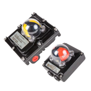
After sending a valve an instruction to open or close, the control system may need to know whether the valve actually reached the required position.
This is where a limit switch box becomes useful.
A limit switch box can provide open and closed position feedback.
For example:
The PLC sends an “open” command.
The actuator turns the valve.
The limit switch confirms that the valve has reached the open position.
The control room can then receive confirmation instead of simply assuming that the valve moved correctly.
This feedback can be particularly important in automated process sequences.
6. Valve Positioner
ON/OFF control is not always enough.
Some processes require a valve to remain partly open.
For example, a process may need the valve at 35% opening to maintain a certain flow rate.
A valve positioner helps control this intermediate positioning.
It compares the requested valve position with the actual valve position and adjusts the actuator until the required position is reached.
Positioners are commonly used in modulating and process-control applications.
7. Air Filter Regulator
Pneumatic actuators need a suitable compressed-air supply.
Plant compressed air can contain moisture, dust, or contamination, and its pressure may not always be ideal for the actuator.
An air filter regulator helps provide cleaner and more controlled air to the actuator.
The filter helps remove contamination, while the regulator helps maintain the required operating pressure.
This small component can have a significant effect on the long-term reliability of a pneumatic automation system.
How Does Valve Automation Work?
Consider a simple automated ball valve.
The process starts with a command.
That command may come from:
- a PLC;
- a DCS;
- an operator switch;
- a level sensor;
- a pressure sensor;
- a temperature controller;
- an emergency shutdown system.
Suppose the system needs the ball valve to close.
The PLC sends an electrical signal to the solenoid valve.
The solenoid valve redirects compressed air into the pneumatic actuator.
The actuator rotates.
The actuator shaft turns the ball valve stem.
The valve closes.
The limit switch then detects the closed position and sends feedback to the control system.
The complete movement may happen without anyone physically touching the valve.
With an electric actuator, the basic control concept is similar, but electricity powers the actuator motor directly instead of controlling compressed air through a solenoid valve.
Pneumatic Valve Automation
Pneumatic valve automation is extremely common in process industries.
A typical pneumatic automated valve assembly may include:
Valve + Pneumatic Actuator + Solenoid Valve + Limit Switch Box + Air Filter Regulator
Additional components may be added depending on the application.
Pneumatic systems are often chosen where compressed air is already available and fast valve movement is required.
A spring-return actuator can also provide a practical fail-safe arrangement.
For example, imagine a line carrying a process fluid that must immediately stop if the control air fails.
A spring-return actuator can be configured so the valve moves toward its safe position when the air supply disappears.
The actual fail-open or fail-close arrangement should always be selected according to process requirements.

For applications that require a ready pneumatic ball-valve automation package, CBT India also offers an ON/OFF Floating Ball Valve System with actuator and pneumatic automation accessories.
Electric Valve Automation
Electric valve automation replaces compressed-air actuation with an electric motor.
A basic automated arrangement may include:
Valve + Electric Actuator + Limit Switches + Control System
Electric actuators can be particularly attractive for remote locations.
Imagine a valve installed far away from the main process area.
Electrical power may already be available, but an instrument-air line may not be.
Instead of installing a long compressed-air pipeline, an electric actuator may provide a simpler solution.
Electric actuators can also offer integrated control and position feedback depending on the selected unit.
However, factors such as power supply, duty cycle, torque, weather protection, hazardous-area requirements, and fail-safe behaviour must still be checked carefully.
Automated Ball Valves
Ball valves are one of the most common valves used in automation.
A ball valve normally requires only a quarter turn to move from fully open to fully closed.
This makes it well suited to rotary actuators.
Automated ball valve systems are used for services such as:
- process isolation;
- water;
- air;
- oil;
- gas;
- chemicals;
- utility systems;
- batching;
- filling systems.
A pneumatic or electric actuator can be selected depending on the required operation.
For pneumatic applications, accessories such as solenoid valves and limit switch boxes can complete the automation package.
For smaller direct-mount pneumatic applications, CBT India also lists a 2-way direct mount metal ball valve with pneumatic actuator.
Automated Butterfly Valves
Butterfly valves are also widely automated.

They are especially common in larger pipe sizes because their design can be compact compared with some other valve types.
An automated butterfly valve may use a pneumatic actuator for fast ON/OFF operation or an electric actuator when electrical control is preferred.
Depending on the process, the system may also include:
- solenoid valves;
- positioners;
- limit switches;
- position transmitters;
- air filter regulators.
This type of complete assembly is commonly used in water, process, utility, chemical, petrochemical, HVAC, and other industrial systems.
ON/OFF vs Modulating Valve Automation
Before selecting any actuator, you need to decide what the valve is supposed to do.
There are two common control requirements.
ON/OFF Automation
The valve only needs two main positions:
Fully open.
Fully closed.
This is common in isolation applications.
A ball valve supplying water to a tank is a simple example.
For these applications, products such as an ON/OFF Floating Ball Valve System can provide a complete automated arrangement when the valve specifications match the process conditions.
Modulating Automation
The valve needs to move to different positions between fully open and fully closed.
For example:
25% open.
50% open.
75% open.
This type of control may be used to regulate flow, pressure, level, or temperature.
Modulating valve automation usually requires more detailed actuator and position-control selection.
How to Select a Valve Automation System
A common mistake is selecting the actuator first.
Start with the process and the valve instead.
Step 1: Identify the Process Media
What is passing through the valve?
Water?
Air?
Steam?
Oil?
Gas?
Chemical?
The media affects the valve body, seat and seal selection.
Step 2: Check Pressure and Temperature
The valve must safely handle the actual operating conditions.
Do not select the automation package only according to pipe size.
Step 3: Identify the Valve Type and Size
Confirm whether the application needs a ball valve, butterfly valve, globe valve, or another type.
For quarter-turn applications, ball valves and butterfly valves are among the most common options for valve automation.
Step 4: Calculate Required Torque
The actuator must provide enough torque to operate the valve reliably.
Valve size alone is not enough to determine actuator torque.
Process pressure, seat design, valve type and operating conditions can affect the torque requirement.
CBT India’s pneumatic actuator range covers different torque and operating configurations for industrial valve automation applications.
Step 5: Decide Pneumatic or Electric
Ask what utilities are available at the installation.
If reliable compressed air is already available, pneumatic automation may be practical.
If electrical power is available but compressed air is not, an electric actuator may make more sense.
Step 6: Decide the Fail-Safe Position
What should happen if the plant loses air or electrical power?
Should the valve:
- fail closed;
- fail open;
- or remain in its last position?
This is an important process-safety decision.
Step 7: Decide ON/OFF or Modulating
A simple isolation valve may only need ON/OFF operation.
A process-control valve may require precise positioning.
Do not pay for unnecessary control features, but do not under-specify a system that needs modulation.
Step 8: Select the Required Accessories
The complete package may require:
- solenoid valve;
- limit switch;
- positioner;
- air filter regulator;
- manual override;
- position indicator;
- proximity switch;
- control accessories.
These should be selected as part of the complete valve automation system rather than added randomly later.
Benefits of Valve Automation
Valve automation can provide several practical benefits.
Remote Operation
Operators can control valves from a control room instead of visiting every valve manually.
Faster Response
Automated valves can react much faster to process signals or emergency commands.
Repeatable Operation
The valve follows the same control logic each time instead of depending on different operators.
Integration With PLC and DCS
Automated valves can become part of a complete plant-control system.
Position Feedback
Limit switches and transmitters can tell the control system whether the valve is actually open or closed.
Fail-Safe Capability
Correct actuator selection can allow the valve to move to a defined safe condition during utility failure.
Reduced Manual Intervention
Automation is especially valuable for valves located in difficult, remote, or frequently operated locations.
Industries Using Valve Automation
Valve automation is used wherever industrial processes require controlled fluid movement.
Common industries include:
- oil and gas;
- petrochemical;
- chemicals;
- pharmaceuticals;
- water treatment;
- power generation;
- food and beverage;
- steel;
- paper and pulp;
- HVAC;
- fertilizer;
- general manufacturing.
The exact automation package changes from one application to another.
A small water-treatment valve may need a simple electric actuator.
A process-plant butterfly valve may need a pneumatic actuator, solenoid valve, limit switch and AFR.
A modulating control valve may need an actuator and positioner.
There is no single valve automation package that is correct for every system.
Common Valve Automation Selection Mistakes
The first mistake is choosing an actuator only by valve size.
Two valves of the same size can require different operating torque.
Another mistake is ignoring the available air pressure.
A pneumatic actuator may look correctly sized on paper, but its actual torque output depends on available air pressure.
Incorrect solenoid-valve selection can also cause problems.
A single-acting actuator and a double-acting actuator may require different pneumatic control arrangements.
Ignoring fail-safe behaviour is another serious issue.
You should know what happens to the valve when power or air is lost before the system is installed.
Finally, avoid treating accessories as an afterthought.
The solenoid valve, limit switch, positioner, AFR, brackets and couplings all affect how the complete automated assembly works.
Final Thoughts
Valve automation is not simply about replacing a hand lever with an actuator.
A reliable automated valve is a complete system.
The valve must suit the media, pressure and temperature.
The actuator must provide the required torque.
The control method must match the application.
The solenoid valve must correctly pilot a pneumatic actuator.
The limit switch must provide the required feedback.
The positioner must control the valve accurately when modulating operation is needed.
And every part must work together.
For simple ON/OFF isolation, the system may only need a ball valve, actuator and basic control accessories.
For a more demanding process, the package may include a pneumatic actuator, NAMUR solenoid valve, limit switch, AFR and positioner.
For electrically operated systems, an electric valve actuator can be selected based on valve torque, voltage, duty cycle, operating speed and control requirements.
The best approach is to select valve automation as one engineered assembly rather than buying individual components first and trying to make them work together later.
Start with the process conditions, decide what the valve needs to do, and then build the automation package around that requirement.
Frequently Asked Questions
What is valve automation?
Valve automation is the use of an actuator and control accessories to operate an industrial valve automatically. The valve can be opened, closed, or positioned through electrical, pneumatic, or control-system signals.
What components are used in valve automation?
A typical system may include an industrial valve, pneumatic or electric actuator, solenoid valve, limit switch box, air filter regulator, positioner, mounting hardware and control system.
Which valves can be automated?
Ball valves, butterfly valves, plug valves, globe valves, gate valves and other industrial valves can be automated when the correct actuator and mounting arrangement are selected.
What is a pneumatic valve automation system?
A pneumatic valve automation system uses compressed air to operate the actuator. It may include a pneumatic actuator, solenoid valve, limit switch, air filter regulator and other accessories.
What is electric valve automation?
Electric valve automation uses an electric actuator to move the valve. It is useful where electrical power is available and compressed air is unavailable or unnecessary.
What is the difference between ON/OFF and modulating valve automation?
ON/OFF automation moves the valve between fully open and fully closed positions. Modulating automation allows the valve to move to intermediate positions to regulate variables such as flow, pressure or temperature.
Why is a limit switch used in valve automation?
A limit switch provides valve-position feedback. It can confirm to a PLC, DCS or other monitoring system whether the valve has reached its open or closed position.
How do I select the right actuator for valve automation?
Check the valve type, valve torque, process pressure, temperature, available utilities, operating speed, fail-safe requirement, cycle frequency, control method and installation environment before selecting the actuator.